
Introduction
This design problem will be divided into three modules: PS/2 Keyboard Controller, Tone Generator, and Song Composer. Each module is essential to the operation of a succeeding module. You are required to show each module separately for checking purposes.
Contents
PS/2 Keyboard Controller
You are to design a PS/2 Keyboard Controller/Wrapper which handles the PS/2 protocol. The goal of this module is to create a simple interface between the PS/2 keyboard and any other device. For checking purposes, this other device will be an LCD controller. You are free to choose whether to implement the controller using logic, picoblaze, or a combination of both.
I/O ports
Aside from the clock and reset ports, your PS/2 keyboard controller should contain the following ports:
- en – (output) enable port. This signal should be set to high whenever a key press event on the keyboard is detected
- data – (output, 8 bits) ASCII data. This signal should be set to the corresponding ASCII value of the key pressed. Special keys with no ASCII equivalents will be discussed in the following sections
- ack – (input) acknowledge. This input signal is driven by the slave device accepting the data sent by the keyboard controller
Operation
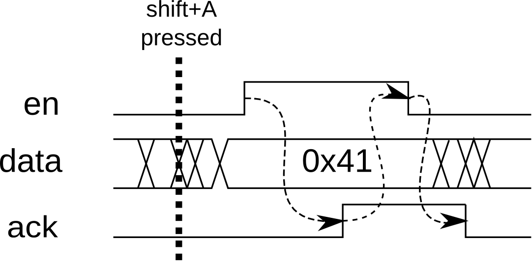 The figure above shows the 2-way handshake protocol between the PS/2 keyboard controller and the slave device. The en and data signals are generated by the PS/2 keyboard controller and the ack signal is generated by the slave device. When the shift+A keystroke occurs, the ASCII code for ‘A’ is placed at the data signal. Afterwards, the en signal is asserted to indicate that the ASCII data is ready. The slave device monitors the en signal periodically. Once it sees the signal asserted, it receives the ASCII code from the data signal and asserts its ack signal. Once the keyboard controller sees the ack signal asserted, it lowers the en signal. Similarly, once the slave device sees the en signal deasserted, it also deasserts the ack signal. Translation of the key presses to ASCII should be done by the controller. For this design problem, we will only be using the 7-bit ASCII equivalents of characters. For simplicity, we will only be limiting the keystrokes to those with ASCII equivalents and some special keys. The special keys that will be supported are the four arrow keys and the backspace key. If a keystroke for an ASCII character is detected, the corresponding 7-bit ASCII code for that character is placed in the 7 least significant bits of the data signal, while a 0 is placed in the most significant bit. For the special keys, the following data values are set:
- up arrow – 0x80
- down arrow – 0x81
- left arrow – 0x82
- right arrow – 0x83
- backspace – 0x84
Because the handshake protocol requires the keyboard controller to wait for an acknowledge signal from the slave, it is necessary to provide an input buffer for the keystrokes. You are required to implement a 64-character input buffer for the keystrokes. You may implement this using either registers or the on-board/on-chip SRAMs.
Slave device
As mentioned earlier, the slave device used for checking this module of the design problem is an LCD controller. Each keystroke’s character will be displayed in the LCD, with the cursor automatically moving to the next character. Pressing the backspace key will move the cursor one character back while erasing (writing a space) to that character’s place. pressing the arrow keys will move the cursor accordingly in the display. To keep the display simple, we will only be using the default character display addresses available at startup (address 0x00-0x0F for the first line, 0x40-0x4F for the second line). The sequence of addresses will be 0x00 to 0x0F, followed by 0x40 to 0x4F, and looping back to 0x00.
Tone Generator
In this module, you will be using the FPGA to generate simple tones using a buzzer or speaker. Since the Spartan 3E Starter Kit does not have a buzzer, we will be connecting a buzzer or speaker externally as shown in the figure below: 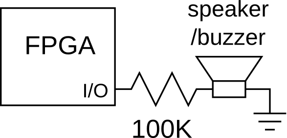 Tones will be generated by setting the output to a periodic square wave. Varying the frequency of the square wave will allow us to generate various tones. For this module, you are expected to generate 13 different tones. The frequencies of the tones will be based on a chromatic scale starting from middle C (C4, ~261.626 Hz) to C5, which is an octave higher (~523.251 Hz). These tones will be mapped to different keyboard buttons. You are required to use the PS/2 keyboard controller in the previous module. Whenever a button is pressed, the tone will be generated until the key is released. The mappings of the tones are as follows:
- C (C4) – a
- C#/Db – w
- D – s
- D#/Eb – e
- E – d
- F – f
- F#/Gb – t
- G – g
- G#/Ab – y
- A – h
- A#/Bb – u
- B – j
- C (C5) – k
Song Composer
The final module will be a song composer similar to those found in old Nokia mobile phones. Input will be through the keyboard while output of the musical score will be through the LCD. Input of notes will be made in the same manner as the tone generator in the previous module. Each note will have a default duration of a quarter note. 4 different note durations should be supported by your composer (whole, half, quarter, eighth). The duration of the current note may be modified by through the ‘z’ and ‘x’ keys of the keyboard. Pressing ‘z’ will decrease the note duration, while pressing ‘x’ will increase it. You will also be supporting more than 1 octave of tones this time. When a note is entered, the default octave is that of the note preceding it. For example, if the previous note entered was E4, the pressing ‘g’ on the keyboard will input a G4. The octave of the current note can be modified by pressing the up and down buttons. Pressing up should raise the note by an octave, while pressing down should lower the note by an octave. The range of notes that should be supported is C3 (~130.813 Hz) to C6 (~1046.502 Hz). The composer should be able to support 128 notes. Also, when inputting and modifying notes, the corresponding tone of that note should be sounded for a certain amount of time. The absolute duration of a note is totally up to you, just make sure that the relative note durations are preserved (i.e. a half note has half the duration of a whole note) The LCD will be used to display the score of the song. We will be using only the upper line of the display. Whenever a note is added, a representation of the note will be displayed on screen. The notation used will follow this format: <duration><tone>. For example, a whole note with a middle C tone will be represented as 1c4, while a quarter note of its sharp will be represented as 4c#4. If the note added will be outside the current display area, the LCD should automatically scroll. Pressing the left and right arrow keys will allow you to move the cursor backward and forward through the score. The current position of the cursor will indicate the currently selected note, which can be modified using the ‘z’, ‘x’, up arrow and down arrow keys. Entering a note while the cursor is in the middle of the score should insert the note accordingly. Pressing the backspace button will delete the note before the currently selected note. Although a single line of the LCD only supports 64 characters, you should still be able to view all 128 notes of the score. Lastly, pressing the ‘p’ key should play the score starting from the currently selected note.
Submission
Deadline for checking is on January 16, 2014. Checking will be done in-class. You may opt to have partial modules checked before the deadline.